Custom
PCBs
I designed a circuit board for a toy, had it made, soldered it, and never finished the toy.
The toy was a treasure detector. Hold the button and it starts beeping. Get closer to something and the beeps speed up. A knob changes the sound. Inside is an ESP32, an ultrasonic distance sensor, a small amp, and a speaker.
This started as a breadboard and a pile of jumper wires. It worked, so I kept going: a printed case, then a second case, then a schematic, then a real circuit board.
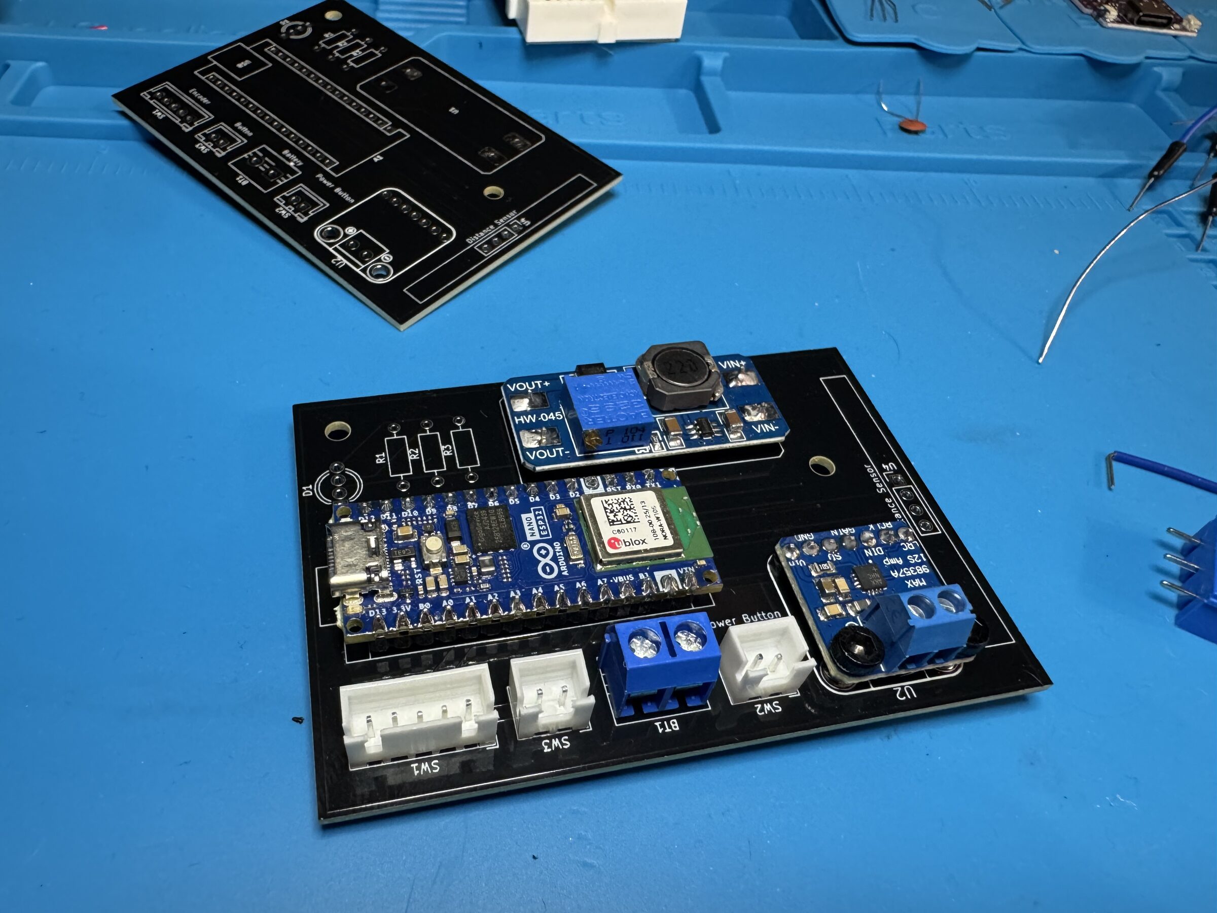
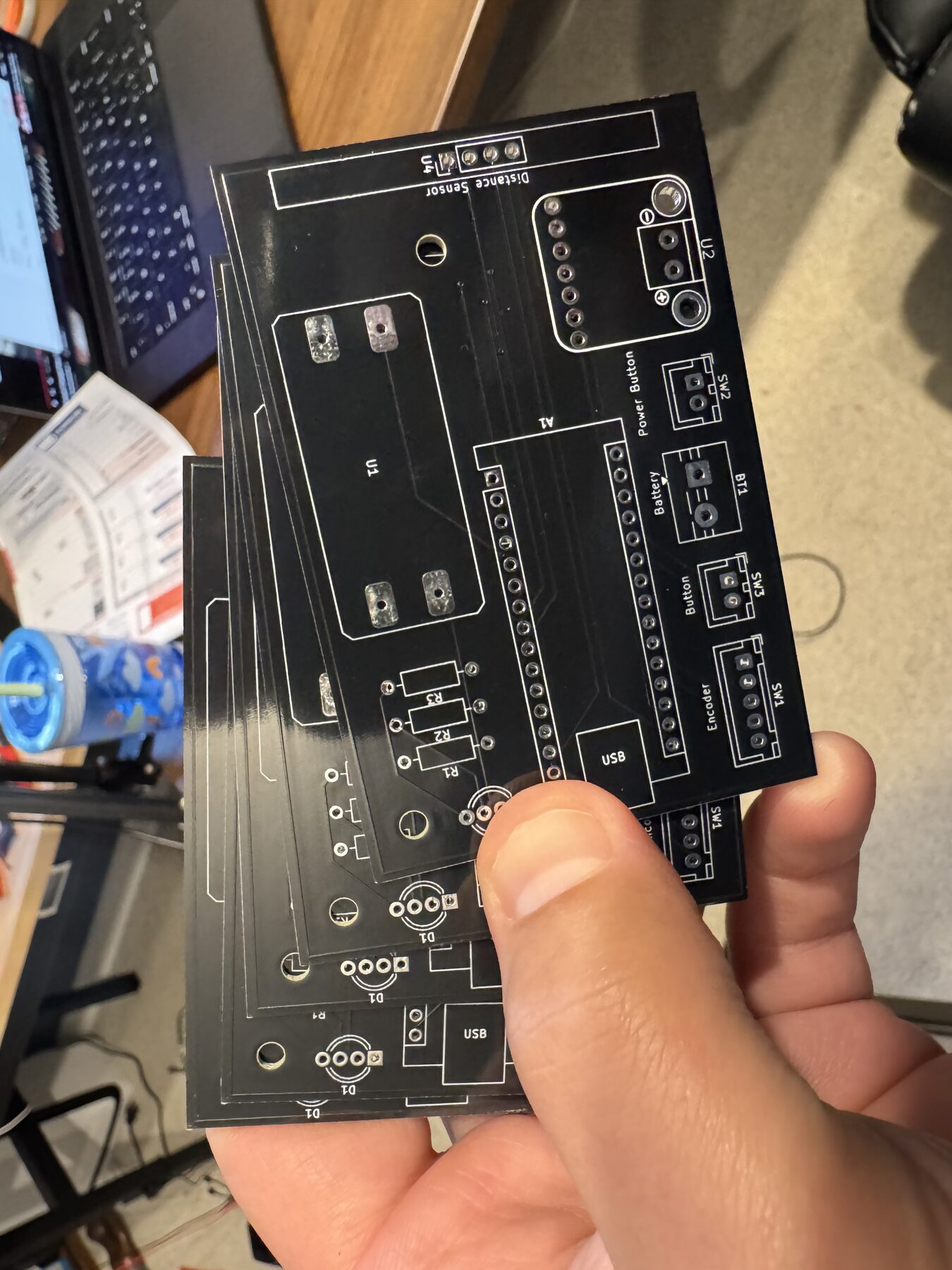
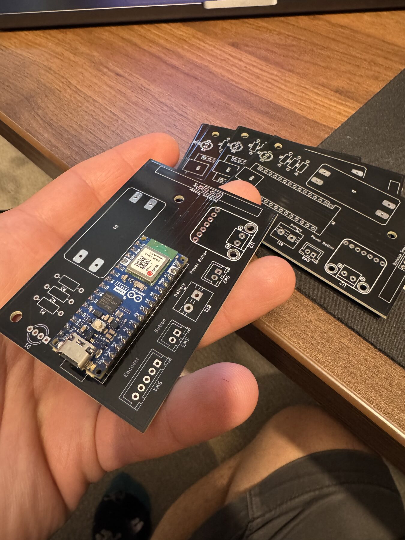
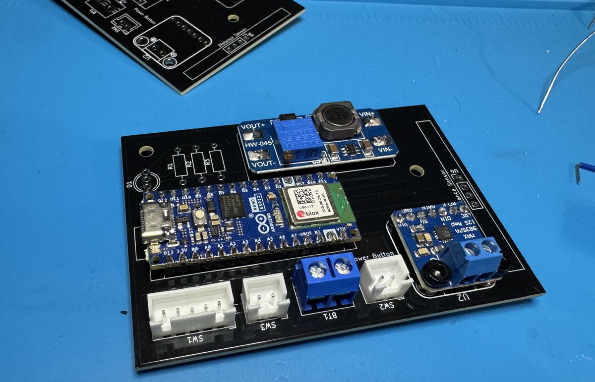
Getting the boards back was my favorite part of the whole project. Every part plugs into a labeled connector, and the mess of wires is gone. It's also why this page is about a toy that doesn't exist yet. The last step was making the cables that connect the board to the button, knob, sensor, and speaker, and I never did it.
The Board
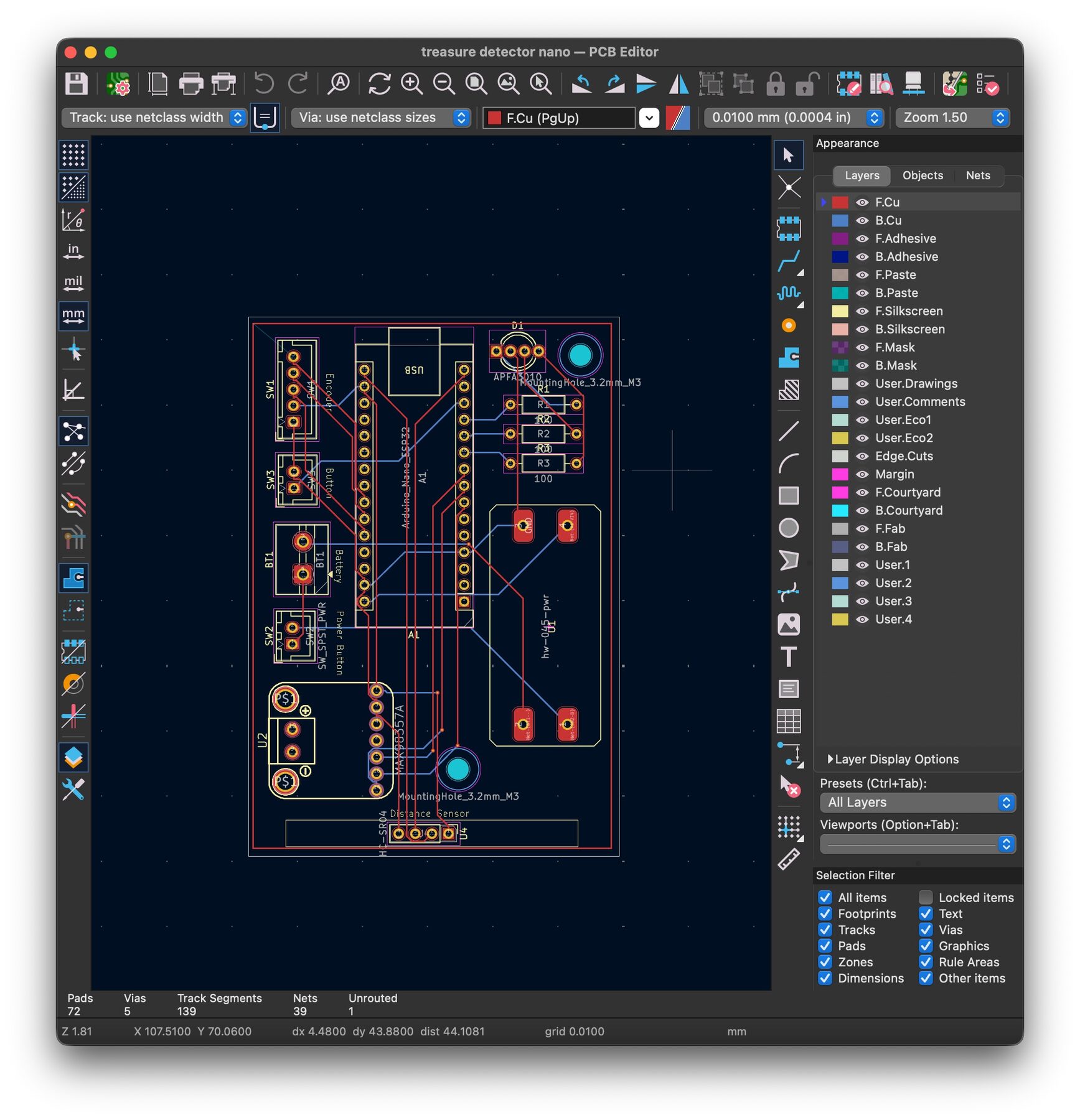
The 3D model straight out of KiCad. The Nano, amp, and boost converter don't have 3D models, so you see their outlines on the silkscreen instead.
Most of the parts are breakout boards I already had on the breadboard, so the PCB is mostly sockets. Everything that lives off the board, like the button, knob, and battery, gets a JST connector with its name printed next to it.
| A1 | Arduino Nano ESP32 | Runs the sketch |
| U4 | HC-SR04 ultrasonic sensor | Measures how close you are |
| U2 | MAX98357A I2S amp | Drives the speaker |
| U1 | HW-045 boost converter | Steps the battery voltage up |
| SW3 | Push button | Hold to scan |
| SW1 | KY-040 rotary encoder | The sound knob |
| SW2 | Power switch | On and off |
| BT1 | Battery terminal | LiPo in |
| D1 | RGB LED, R1–R3 100Ω | Color shows how close you are |
From Schematic to Board
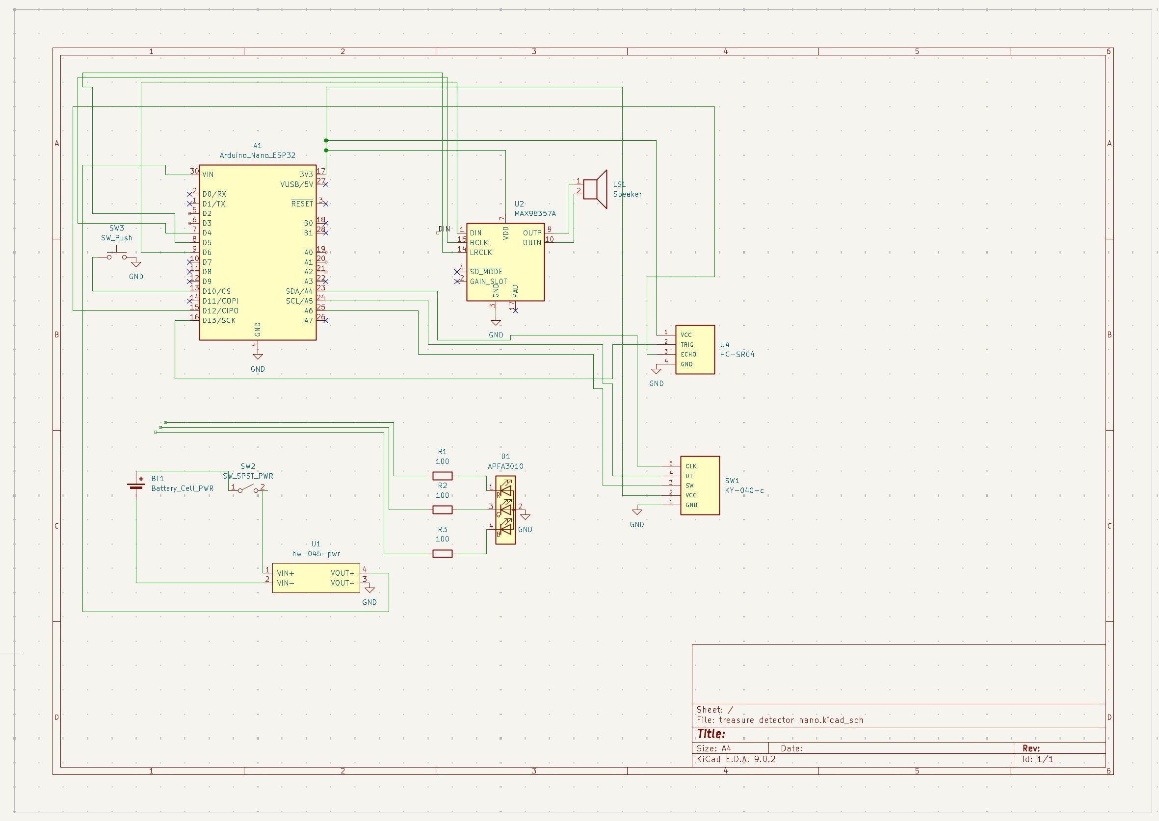
Everything was drawn in KiCad 9. One schematic sheet, then a two-layer board laid out around the modules.
Back From the Fab
Two Enclosures
Version 1
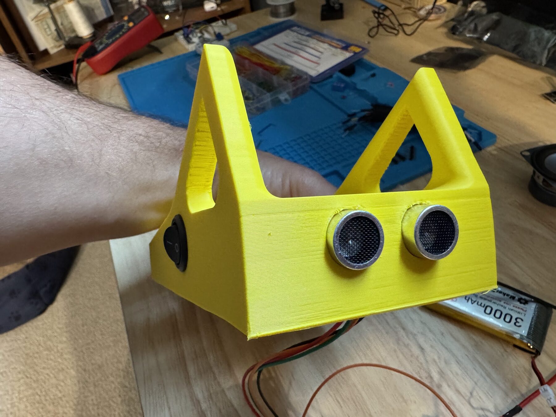
The first case was built around the breadboard parts. The ultrasonic sensor's two transducers became the eyes, and the scan button went on the side.
Version 2
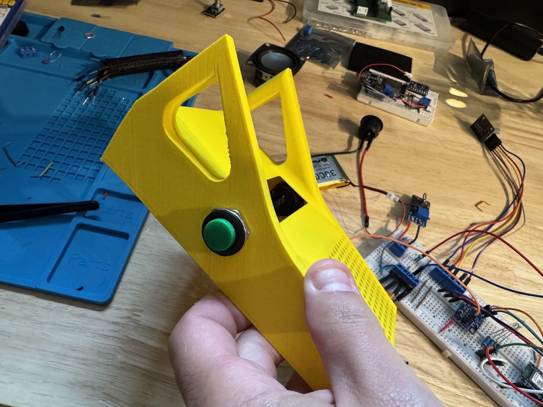
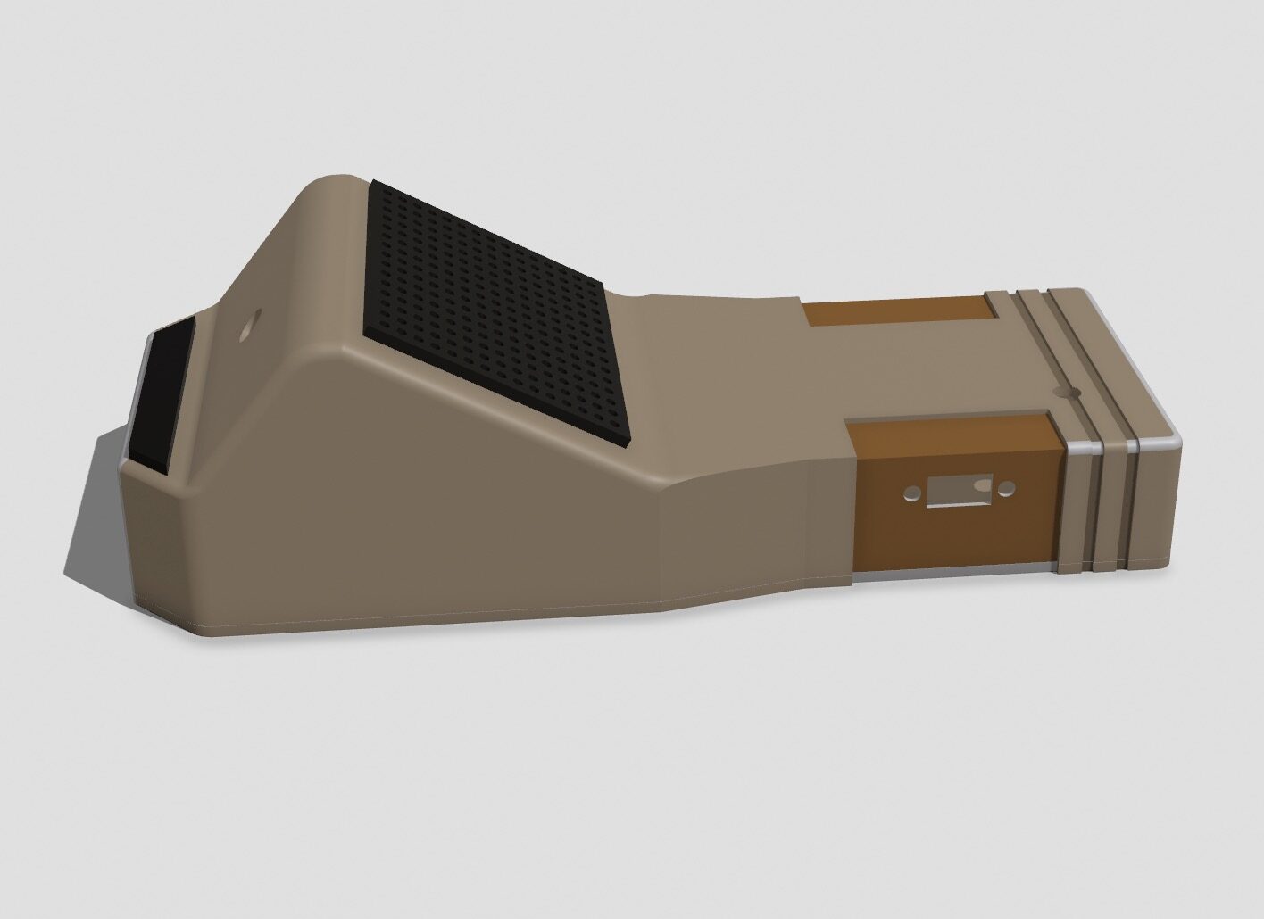
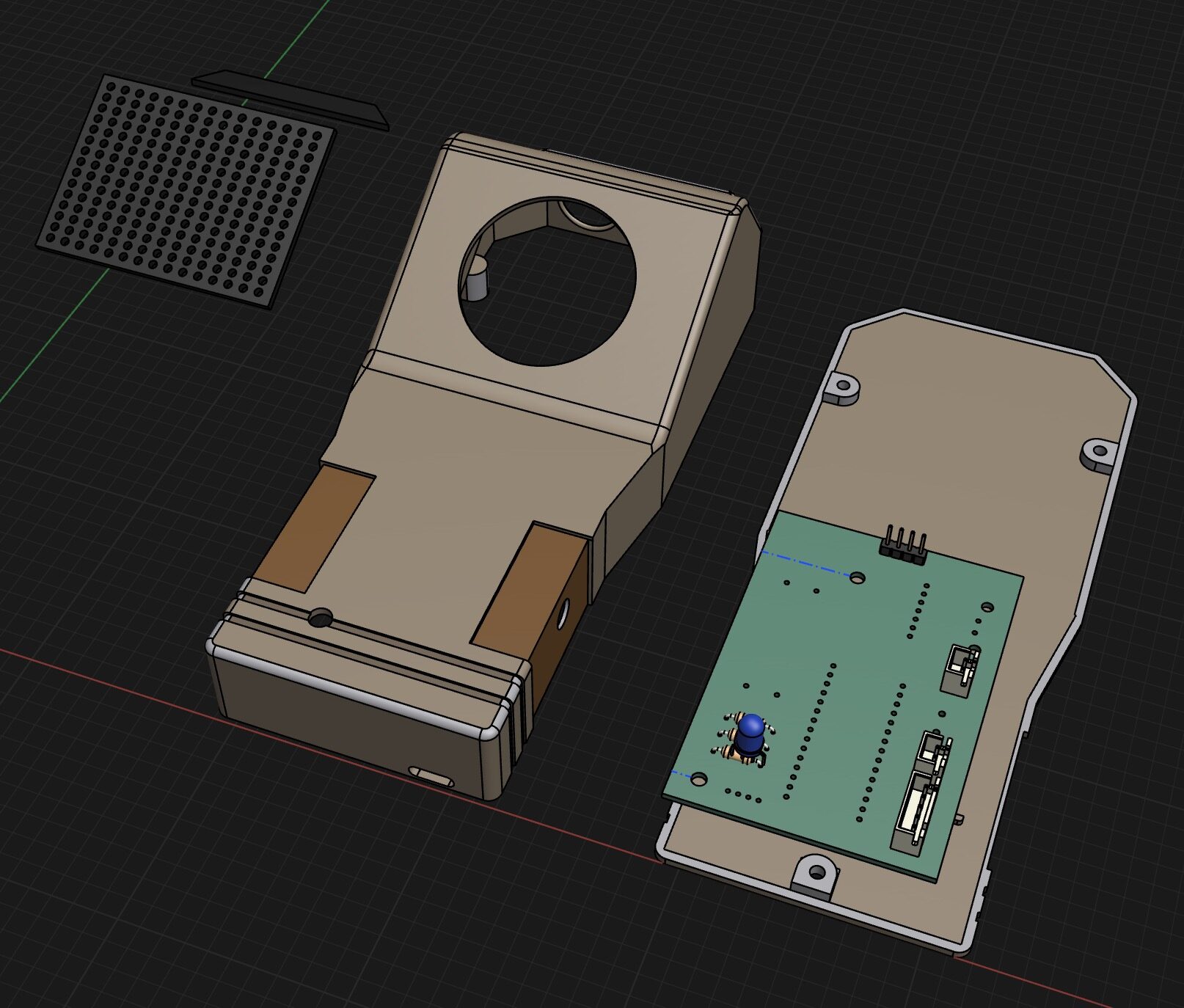
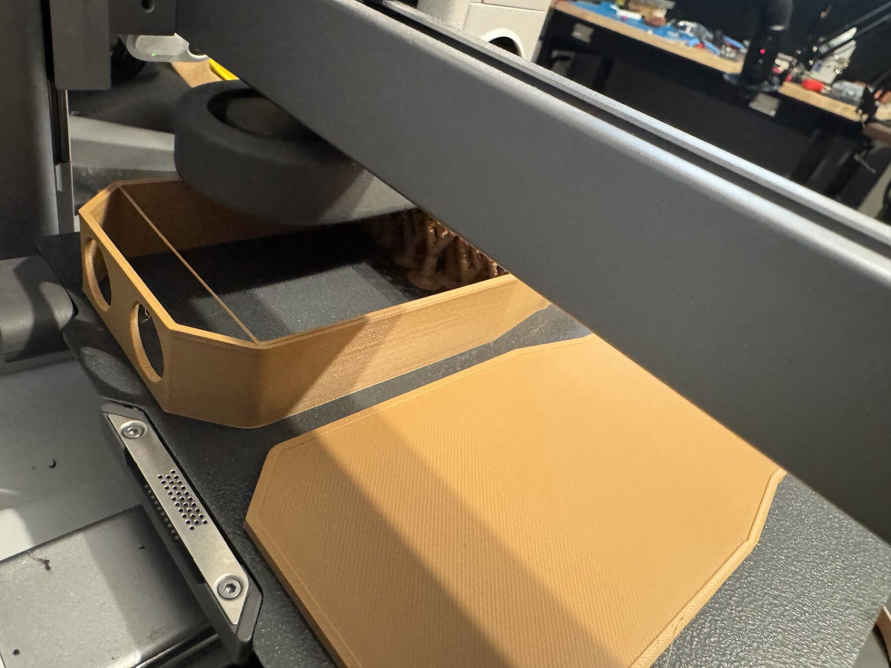
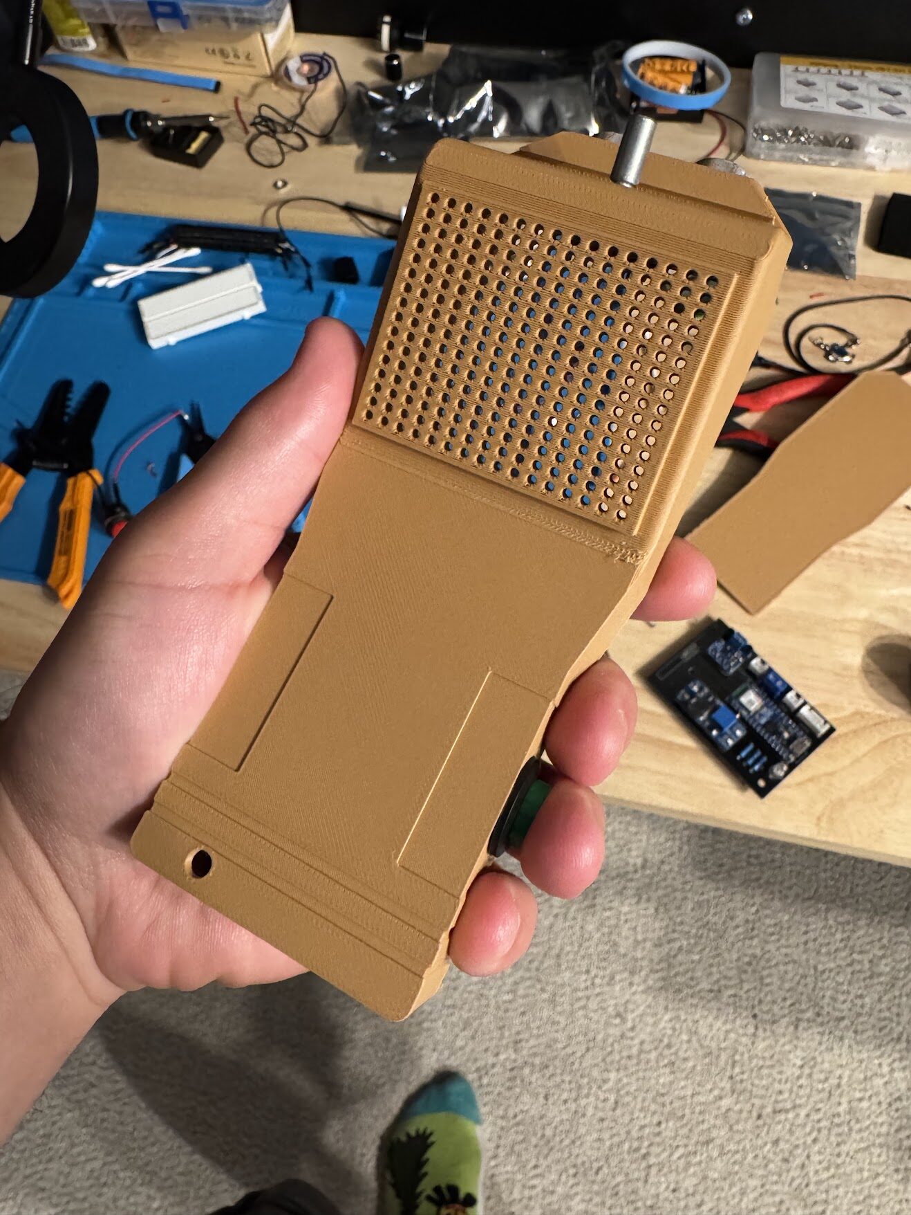
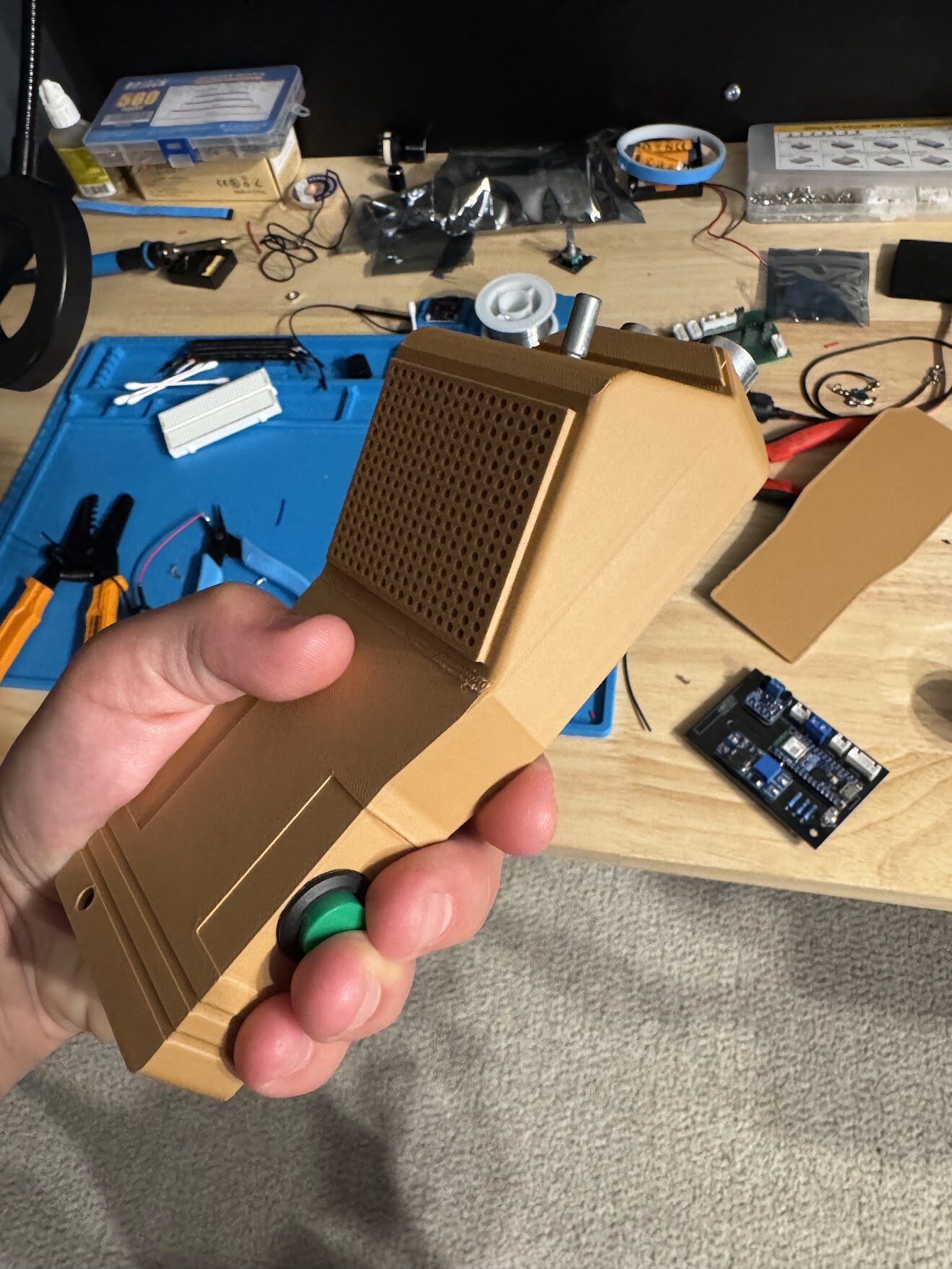
Once the PCB was on its way, I designed a handheld case around it. The board screws to the bottom shell, the speaker sits under a grille on top, the knob sticks out the front, and the scan button is where your thumb lands.
The Code
The firmware is one Arduino sketch. While the button is held, the loop reads the distance sensor, picks a beep speed and an LED color, and plays a short sine-wave beep out of the ESP32's DAC.
This is the breadboard version, which ran the speaker through the DAC and a transistor. The PCB moved to a Nano ESP32 and an I2S amp, and the sketch never got updated for it. The knob is read, but not hooked up to the sound yet.
| Distance | LED | Beep |
|---|---|---|
| Over 24 in | Red | Every 800 ms |
| 4 to 24 in | Blue | Every 150 ms |
| Under 4 in | Green | Every 50 ms |
#include <RotaryEncoder.h>
#include <Arduino.h>

// Amp Transistor
// amp L -> emitter (left)
// 14 -> resistor -> base (center)
// 25 (DAC) -> collector (right)

// Distance Sensor echo
// Echo -> 2k Resistor -> 22
// Echo 2k Resistor -> 1k Resistor -> Ground

// PINS
const int speakerPin = 25; // transistor collector
const int ampPin = 14; // transistor base
const int buttonPin = 32;
const int trigPin = 33;
const int echoPin = 22;
const int ledRedPin = 18;
const int ledGreenPin = 19;
const int ledBluePin = 21;
const int encoderClkPin = 17;
const int encoderDtPin = 15;
const int encoderSwPin = 16;

const int toneFrequency = 440;
const int farAwayInterval = 800;
const int farAwayVolume = 70;
const int closerInterval = 150;
const int closerVolume = 80;
const int superCloseInterval = 50;
const int superCloseVolume = 120;
const int LEDC_BASE_FREQ = 5000;
const int PWM_FREQ = 20000;     // 20 kHz
const int PWM_RES = 8;          // 8-bit resolution

// dynamic global variables
int currentLed = ledRedPin;
bool playing = false;
int encoderLastPos = -1;
float currentDistance = 0;
int currentVolume = farAwayVolume;
int currentSoundInterval = farAwayInterval;
float globalVolume = 0.3; // 80% normal volume

// classes
RotaryEncoder encoder(encoderClkPin, encoderDtPin);

void setup() {
  Serial.begin(115200);
  delay(1000);
  Serial.println("Starting sketch...");

  pinMode(buttonPin, INPUT_PULLUP);
  pinMode(trigPin, OUTPUT);
  pinMode(echoPin, INPUT);
  pinMode(ampPin, OUTPUT);
  pinMode(encoderSwPin, INPUT_PULLUP);
  pinMode(encoderClkPin, INPUT);
  pinMode(encoderDtPin, INPUT);
  ledcAttachChannelAdvanced(ledRedPin, 20000, 8, 0, 1);
  ledcAttachChannelAdvanced(ledGreenPin, 20000, 8, 1, 1);
  ledcAttachChannelAdvanced(ledBluePin, 20000, 8, 2, 1);

  // silence on the DAC
  silenceDac();

  startupSequence();
}

void loop() {
  handleEncoder();

  if (mainButtonDown()) {

    // We don't want to continuously turn on the amp pin
    if (!playing) {
      Serial.println("Button held");
      digitalWrite(ampPin, HIGH);
      playing = true;
    }

    float distance = measureDistanceInches();
    currentDistance = distance;

    Serial.print("Distance: ");
    Serial.print(distance);
    Serial.println(" inches");

    if (distance < 4.0 && distance > 0.0) {
      currentLed = ledGreenPin;
      currentVolume = superCloseVolume;
      currentSoundInterval = superCloseInterval;
    } else if (distance < 24.0) {
      currentLed = ledBluePin;
      currentVolume = closerVolume;
      currentSoundInterval = closerInterval;
    } else {
      currentLed = ledRedPin;
      currentVolume = farAwayVolume;
      currentSoundInterval = farAwayInterval;
    }

    playPattern();

  } else {
    if (playing) {
      Serial.println("Button released.");
      playing = false;
      silenceDac();
      delay(10); // debounce
    }

    if (digitalRead(ampPin) == HIGH) {
      digitalWrite(ampPin, LOW);
    }
  }
}

void startupSequence() {
  int delayMs = 200;
  ledReset();

  ledcWrite(ledRedPin, 255);
  delay(delayMs);
  ledReset();

  ledcWrite(ledGreenPin, 255);
  delay(delayMs);
  ledReset();

  ledcWrite(ledBluePin, 255);
  delay(delayMs);
  ledReset();

  digitalWrite(ampPin, HIGH);
  playSweepBeep(500);
  delay(500);
  silenceDac();
  digitalWrite(ampPin, LOW);
}

bool mainButtonDown() {
  return digitalRead(buttonPin) == LOW;
}

bool mainButtonUp() {
  return digitalRead(buttonPin) == HIGH;
}

void handleEncoder() {
  encoder.tick();
  int newPos = encoder.getPosition();
  if (newPos != encoderLastPos) {
    encoderLastPos = newPos;
  }

  if (digitalRead(encoderSwPin) == LOW) {
    Serial.println("Button Pressed");
    delay(200);
  }
}

float measureDistanceInches() {
  digitalWrite(trigPin, LOW);
  delayMicroseconds(2);
  digitalWrite(trigPin, HIGH);
  delayMicroseconds(10);
  digitalWrite(trigPin, LOW);

  long duration = pulseIn(echoPin, HIGH, 30000);  // timeout at ~30ms
  float distanceCm = duration * 0.034 / 2.0;
  float distanceIn = distanceCm * 0.3937;
  return distanceIn;
}

void ledReset() {
  ledcWrite(ledRedPin, 0);
  ledcWrite(ledGreenPin, 0);
  ledcWrite(ledBluePin, 0);
}

void playPattern() {
  int interval = currentSoundInterval;
  unsigned long start = millis();
  unsigned long lastBeepTime = 0;
  float beepDuration = 0.8 * interval;
  bool ledOn = false;
  bool beepActive = false;

  while (millis() - start < interval) {
    handleEncoder();

    // while playing, if we release the button, break out of the loop
    if (mainButtonUp()) {
      playing = false;
      break;
    }

    unsigned long now = millis();

    if (!beepActive && now - lastBeepTime >= interval) {
      // Time to start the beep
      turnOnLed();

      playSweepBeep(beepDuration);
      lastBeepTime = now + interval;
      ledOn = true;
      beepActive = true;
    }

    // Turn off LED after interval
    if (beepActive && now - lastBeepTime >= interval) {
      if (ledOn) {
        turnOffLed();
        ledOn = false;
      }
      beepActive = false;
    }
  }

  ledReset();
}

void turnOnLed() {
  ledReset();
  ledcFade(currentLed, 0, 4095, currentSoundInterval / 2);
}

void turnOffLed() {
  ledcFade(currentLed, 4095, 0, currentSoundInterval / 2);
}

void silenceDac() {
  dacWrite(speakerPin, 128);
}

void playSweepBeep(int beepDuration) {
  // Center the DAC before playing
  dacWrite(speakerPin, 128);

  unsigned long start = millis();
  int freq = 400;  // Hz

  while (millis() - start < beepDuration) {
    for (int i = 0; i < 360; i += 10) {
      float radians = radians(i);
      int val = sin(radians) * 127 + 128;  // Full waveform swing

      val = constrain(val, 0, 255);
      dacWrite(speakerPin, val);
      delayMicroseconds(1000000 / (freq * 36));
    }
  }

  // Silence the DAC when done
  dacWrite(speakerPin, 128);
}Where It Stopped
- Done: Breadboard prototype that beeps faster as you get closer
- Done: Arduino sketch for the sensor, LED, and sound
- Done: Two 3D-printed enclosures
- Done: KiCad schematic and PCB layout
- Done: Boards ordered, delivered, and soldered
- Not done: Wire harnesses from the board to the button, knob, sensor, and speaker
- Not done: Put it in the case and hand it to a kid
Not Optimizing for Finishing
Every step I took made the toy better and moved the finish line further away.
The breadboard worked. Instead of putting it in a box, I designed a box. Instead of wiring that box by hand, I designed a circuit board. The board brought new parts, which meant the code needed changes, which meant the case needed changes. I learned something from every one of those steps. None of them got the toy into a kid's hands.
The step I skipped was the boring one: crimping a handful of connectors. If I had been trying to finish, I would have put the breadboard in the first case, called it done, and made the PCB for version two.
I still love these boards. Seeing your own silkscreen on a real PCB is a great feeling, and it's the cleanest way I know to get rid of a nest of wires. Now I just do it after the thing works in a box. The LED Matrix Visualizer is what that looks like when I actually finish.